In this section, we’ll review how active, reference, and ground electrodes work in EEG recordings. You can find a detailed discussion in Chapter 5 of Luck (2014). Here, I’ll explain the concepts using the artificial ERP waveforms shown in Figure 5.1. It helps to use artificial data in this context because we know what the true signals are. Later in the chapter, you’ll apply what you’ve learned to real data.
In the artificial example shown in Figure 5.1A, the generator dipole is represented by the arrow, with the positive side pointing toward the Pz electrode. The broken line represents the transition between the positive and negative sides of the dipole, and the voltage is zero along this line. Unfortunately, we don’t know the location of this zero line when we’re looking at real data, and we don’t have a single zero line when more than one dipole is active (which is almost always the case).
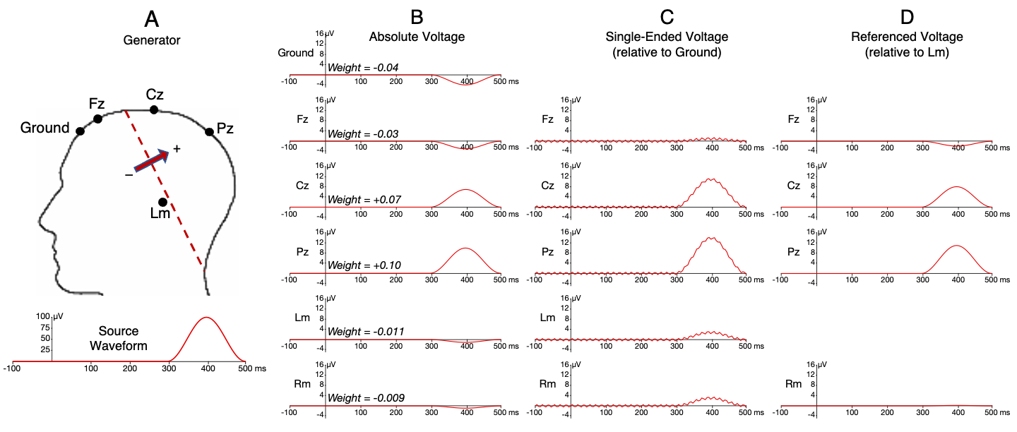
Figure 5.1. Example of active, ground, and reference electrodes. (A) Generation of the ERP. The arrow represents the generator dipole, and the source waveform shows the change in voltage over time at this dipole. The broken line represents the band of zero voltage at the transition between the positive and negative sides of the dipole. (B) Absolute voltage at each electrode site (which is known in this simulation but cannot be directly recorded). The absolute voltage at a given site is the source waveform multiplied by the weight for that site. (C) Single-ended voltage at each electrode site (i.e., the potential between a given site and the ground electrode). In most systems, this signal is present only inside the amplifier and is not available in the system’s output. Note that a small amount of 60 Hz noise from the amplifier’s ground circuit contaminates these signals. (D) Voltage at each site referenced to the left mastoid (Lm) electrode. This signal is obtained by subtracting (either in hardware or in software) the single-ended Lm signal from the signal at each of the other electrodes.
Voltage is the potential (pressure) for charges to move from one place to another place, so there is no such thing as the voltage at a single electrode site. However, it is convenient to use the term absolute voltage to refer to the potential between one electrode and the average of the entire surface of the head. We use the average of the surface of the head in our definition of absolute voltage because the average voltage across the entire surface of the head is assumed to be zero. This assumption is true only for perfectly spherical heads (Yao, 2017), but it is a reasonable approximation for our present purposes.
Figure 5.1B shows the absolute voltage that we would expect at each of our recording electrodes. The absolute voltage at a given electrode site is equal to the source waveform multiplied by a weighting factor that represents the degree to which voltage is conducted from the specific generator to a given electrode site. For example, we’re assuming that 10% of the voltage from the generator dipole is conducted to the Pz electrode site, so the weight for that site is 0.10. The source waveform has a peak amplitude of 100 µV, so the absolute voltage waveform at Pz peaks at 10 µV. The weights are negative for the electrodes on the negative side of the dipole, so the waveforms are negative-going at those sites. (The weights shown in Figure 5.1A are not the true weights, but are just examples that produce nice round numbers.) If this set of concepts about ERP generation is unfamiliar to you, you can learn more by reading Chapter 2 of Luck (2014) or by taking my online Introduction to ERPs course.
There is no way to measure the absolute voltage at a given electrode site. The absolute voltage is just a convenient hypothetical entity for explaining how reference electrodes work. The EEG amplifier would actually measure the voltage between each electrode site and the ground electrode. The voltage between two electrodes is simply the difference between the absolute voltages at those two sites. For example, the absolute voltage at Pz peaks at 10 µV and the absolute voltage at the ground electrode peaks at -4 µV, so the voltage between Pz and ground is 14 µV (10 minus -4). We call the voltage between a given site and the ground electrode, which is what an EEG amplifier actually measures, the single-ended signal (shown in Figure 5.1C).
EEG amplifiers contain noise in the ground circuit (which is the part of the amplifier that the ground electrode is connected to). Because all electrodes are initially measured with respect to the ground electrode, the noise in the ground circuit is present with approximately equal amplitude in the single-ended signals from all of the electrode sites. In Figure 5.1C, I added some 60 Hz noise to every signal to simulate this noise. However, this noise is often much muchmuch larger, obscuring the actual EEG signals.
EEG recording systems therefore contain differential amplifiers, which use a trick to subtract away the noise from the ground circuit. The trick is to use another electrode as the reference electrode. The single-ended signal at the reference electrode is also recorded relative to the ground electrode, so it also contains the noise from the ground circuit. Consequently, if we subtract the reference electrode signal from the signals at our other electrodes (our active electrodes), the noise is approximately the same in the active and reference electrodes, so the noise is subtracted away. This is shown in Figure 5.1D, in which the single-ended signal from the left mastoid (Lm) electrode is subtracted from the signal at each of the other electrodes to create a referenced or differential signal. You can see that the referenced waveforms no longer have the 60 Hz noise that is visible in the single-ended signals. If you didn’t follow this brief overview of referencing, you can watch this brief video from the online Introduction to ERPs course or read the more detailed description in Chapter 5 of Luck (2014).
In most EEG systems, the referencing subtraction is performed in the amplifier’s hardware, so you have no way of accessing the single-ended signals. You’ll only ever see the referenced signals. There are, however, some exceptions. The BioSemi ActiveTwo system (which we used for the ERP CORE experiments) does not subtract the reference in hardware and instead outputs the single-ended signals. The researcher then subtracts the reference from the single-ended signals in software, after the recording session is over. During the recording, this system will show the referenced signals on the screen (to minimize noise from the ground circuit), but only the single-ended signals are saved to the file. This confuses many researchers, who do not realize that the saved data has not been referenced. If you use BioSemi, don’t forget to subtract the reference! The Brain Products ActiCHamp system also obtains the single-ended signals, but the data collection software performs the referencing subtraction before the data are saved to a file. This is less confusing.
Yes, I’m a control freak
For recording the EEG from the ActiCHamp system, Brain Products provides an open source program called Pycorder in addition to their closed source Recorder software. My lab has modified the Pycorder software so that we can save the single-ended signals instead of the referenced signals. We then do the referencing offline in software. This produces the same end result that we would get by saving the referenced data, but I like having the raw single-ended data and doing the referencing myself. I guess I’m a bit of a control freak…
In the example shown in Figure 5.1, the Lm electrode is near the zero line for the generator dipole. As a result, the referenced voltages at each site are close in amplitude to the absolute voltages. However, that will not typically be the case, so you shouldn’t assume that the referenced voltages are a good approximation of the absolute voltages. Instead, you should always think of the voltage at a given electrode site as being the difference between the signal at the so-called active electrode and the signal at the so-called reference electrode. I use the phrase “so-called” here because we are simply making a difference between two sites, and both contribute equally to the referenced voltage. If there is a large deflection in the absolute voltage in the reference electrode, than an inverted version of this deflection will be present at every so-called active site. (It’s inverted because we subtract the reference.) So, when you see a waveform labeled “Cz”, you are not looking at the voltage at the Cz electrode site. You are looking at the potential between the Cz site and the reference site, which is equivalent to the absolute voltage at Cz minus the absolute voltage at the reference site. The so-called active and so-called reference sites are equal contributors to this voltage. In fact, in some areas of research, Cz is used as the reference (which is equivalent to inverting the waveform). It’s therefore more accurate to say that a waveform is from the “Cz channel” rather than from the “Cz electrode”.
If there is one thing I hope you learn from this chapter, it’s that you need to think of a given ERP waveform as equally reflecting signals from the so-called active and so-called reference sites, not as being primarily from the active site. The reference site you choose for your analyses can have a huge impact on how the waveforms look and which channels show the experimental effects. Unfortunately, there is no perfect reference site. In most cases I recommend simply using whatever is common in your subfield. That way, your data can be compared with the data from other studies. If you use a different reference site, your data may end up looking quite odd, and you may think that you’ve discovered new effects.