Now let’s see how re-referencing is accomplished in ERPLAB with the data from the N400 ERP CORE experiment. To keep things simple for this exercise, we’ll just work with the grand average ERPs.
Launch EEGLAB and set the current directory to be the Chapter_5 folder. Load the file named Grand_N400_diff.erp using EEGLAB > ERPLAB > Load existing ERPset. Plot the data from Bins 3, 4 and 5 (EEGLAB > ERPLAB > Plot ERP > Plot ERP waveforms). The waveforms should look familiar from the previous chapters. As before, Bins 3 and 4 are the related and unrelated target words, respectively. Bin 5 is the unrelated-minus-related difference wave. You can see a big beautiful N400 (especially in the difference wave), with the biggest N400 in the CPz channel.
But remember, the waveform in a given channel is determined just as much by the reference electrode as by the active electrode, even though the active electrode is typically used to name the channel. Unless we know what was used as the reference, we don’t really know what we’re looking at in this plot. When I’m reading a journal article, I go to the Method section and find out what was used as the reference before I look at any of the waveforms. If you look at the Method section for the paper on the ERP CORE (Kappenman et al., 2021), you’ll see that we used the average of the P9 and P10 electrode sites as the reference for the N400 experiment (and most of the other experiments). P9 and P10 are quite close to the left and right mastoids, so the waveforms look almost identical to what we would have gotten using the average of Lm and Rm as the reference. However, it’s easier to get a good electrical connection with P9 and P10, so we’re starting to use these electrodes as our standard reference sites.
Once you understand that referencing is just a matter of subtraction, you can use some very simple algebra to figure out how to re-reference data that have already been referenced. To demonstrate, we’re going to re-reference the N400 data to the Cz electrode site. Almost all N400 studies use the mastoids (or something nearby) as the reference, so Cz would be an unusual choice for an N400 experiment. However, Cz is used as the default reference in some EEG recording systems (e.g., the EGI system), so it’s easy to imagine that someone would look at N400 data with a Cz reference (especially someone who didn’t understand the importance of the reference location). As you’ll see, the data look quite different with a Cz reference.
Let’s start with the algebra. I’m not much of a math person, so I promise it will be simple. For the CPz channel, the waveforms that you just looked at—with the average of P9 and P10 as the reference—can be expressed conceptually as:
In other words, the referenced voltage at CPz is just the absolute voltage at CPz minus the average of the absolute voltages from P9 and P10. That’s not how the referenced CPz channel was actually created, but it’s conceptually equivalent. Here’s the corresponding expression for the Cz channel:
Our goal is to re-reference the CPz channel so that Cz is now the reference. In other words, we want to create a new channel defined as:
CPzReferenced = CPzAbsolute - CzAbsolute
It turns out that we can get this by just taking the data that have been referenced to the average of P9 and P10 and subtracting Cz from each channel. For CPz, this gives us:
The original reference is in both signals, so it drops out when we do the subtraction. Pretty cool, eh? I think so. But maybe that’s why I’ve spent much of my adult life doing ERP research.
Okay, let’s try it. With Grand_N400_diff.erp as the active ERPset, select EEGLAB > ERPLAB > ERP Operations > ERP Channel Operations. Clear out any equations that remain in the text box from the last time you used this routine. Then change the Mode from Modify existing ERPset to Create new ERPset. We used the Modify existing ERPset mode previously when we added a new channel that was the average of several existing channels. But now we don’t want to add new channels to our existing set of channels—we want to create a brand-new ERPset in which all of the channels have Cz as the reference. Otherwise we would have a huge number of channels in our ERPset.
When we create a new ERPset, we use nch (short for “new channel”) to indicate the new channels that we’re creating and ch to indicate the original channels. For our first channel, FP1, we would subtract the original Cz channel (ch21) from the original FP1 channel (ch1) to create the new channel (nch1). The formula we would enter into the Channel Operations GUI would therefore be:
nch1 = ch1 - ch12 Label FP1
We would then repeat this for channels 2-28. Channels 29 and 30 are the horizontal and vertical electrooculogram (EOG) channels, which use a different reference, so we would just create new channels that are exact copies of the original channels for these sites.
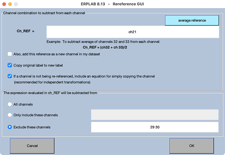
To avoid typing all these equations, click the Reference assistant button. You’ll see a new window that looks like Screenshot 5.1. If you type ch21 in the text box labeled Ch_REF near the top of the window, the Reference assistant will create appropriate equations using ch21 as the reference for every channel. Make sure that the check boxes are set as shown in the screenshot. Also, select Exclude these channels and put 29 30 in the text box, which will cause it not to create re-referencing equations for the horizontal and vertical EOG channels. Then click OK.
Screenshot 5.1
Now the main Channel Operations window should be filled with equations, as shown in Screenshot 5.2 (but note that you may need to scroll the equations window to see all the equations). The equation for each channel simply creates a new channel that is the original channel minus channel 21 (Cz). However, channels 29 and 30 just copy the original horizontal and vertical EOG channels without changing the reference.
Screenshot 5.2
You can now click RUN to execute this set of equations. Because you’ve selected the Create new ERPset option, you’ll see the usual window for saving a new ERPset. It will suggest a name composed of the original ERPset name with _chop (for “channel operations”) appended to the end. However, this is just a suggestion, and it’s often good to use a more informative name. Let’s use _CzRef instead of _chop. You should save it as a file if you’re not going to do the next step right away.
Channel Operations and the ERPLAB Design Philosophy
Creating a separate equation for each channel might seem overly complicated. After all, we’re applying the same operation to almost every channel, so there’s considerable redundancy in the list of equations. Other EEG/ERP analysis systems have much more concise ways of specifying how to re-reference the data. However, by specifying a literal equation for each channel, you know exactly what the operation is doing to your data. In other systems, it’s not obvious exactly what the software is doing when you re-reference the data. In fact, when I’ve used other systems, I’ve resorted to passing artificial data through the re-referencing procedure so that I could figure out exactly what it was doing. In ERPLAB, you write the equations for re-referencing, so there is no uncertainty about how the re-referencing works. This reflects one of our core design philosophies when we created ERPLAB: No magic! We want researchers to know exactly what our software is doing to their precious data.
As an example of this philosophy, check out our documentation page on Timing Details. When you say you want to measure the mean amplitude between 300 and 500 ms, what happens if your sampling rate is 256 Hz and you don’t have time points at exactly 300 and 500 ms? We describe the exact algorithm that we use to round up or down.
The equation approach we use in Channel Operations has another benefit: It’s incredibly flexible. You can perform all kinds of interesting transformations of the data, going way beyond re-referencing. For example, you can take the absolute value of a channel to rectify it (which is useful if you have a channel that contains EMG data). You can create a new channel with the global field power (Skrandies, 1989), as will be described below. You can compute the difference between two channels. And, as you saw in Chapter 3, you can create a new “cluster” channel that is the average of a subset of your channels. To see the possibilities, click the Equation examples button in ERP Channel Operations.
Now plot the data from Bins 3–5. You will see that the Cz channel is now flat, because a channel minus itself is zero. You’ll also see that most of the channels now have a more positive voltage for the unrelated targets than for the related targets, and the unrelated-minus-related difference is now positive instead of negative. In other words, with Cz as the reference, we have a P400 instead of an N400! Moreover, rather than being largest in the CPz channel, the unrelated-minus-related difference is now largest in the F7 channel.
Next, let’s re-reference the data using Oz as the reference. That is, follow the same steps you used to re-reference the data to Cz, but use ch12 instead of ch21 as the reference site and name the ERPset Grand_N400_diff_OzRef. When you plot the data, you’ll see a small N400 in the CPz channel and an opposite-polarity “P400” in the F7 channel. So, you can see that the choice of the reference determines whether a given ERP component is positive, negative, or positive at some sites and negative at others. The reference electrode also impacts which channel has the biggest effects. It really matters!